Updated: April 04, 2022
If you are an experienced welder, you are well aware of the symbols used in welding, but people who are new to the industry or who may just want to learn more are likely to be clueless about the symbols. The truth is that even if you are not a professional welder, understanding the symbols can be important because you may eventually be around an area where welding is being performed. It makes sense to protect yourself and provide for your safety, and understanding the welding symbols can help you to do just that.
It’s important to address a few notes before diving into the symbols. The first of these is that not every welding symbol that is used will be provided in this article. There are many of them, but having a clear idea of most of the essential symbols and what they mean is important.
In addition, the method described in this article is directly related to the United States. The symbols and lettering are what you would find if you were welding in the United States. In other countries they may use other types of symbols. Be aware of that.
 The purpose of the symbols is to indicate what welding processes are specifically being used in the joining of metals. The symbols tell whether this is a localized weld, geared toward a specific area, or whether it is the universal welding process that is used. It also depicts whether the weld was conducted in the field at the site or has been done in shop. The contour of the weld is also depicted.
There are several basic welding symbols. There are five main types, which include arc and gas weld symbols, induction and flow weld symbols, forbe thermit, brazing, and resistance weld symbols.
The purpose of the symbols is to indicate what welding processes are specifically being used in the joining of metals. The symbols tell whether this is a localized weld, geared toward a specific area, or whether it is the universal welding process that is used. It also depicts whether the weld was conducted in the field at the site or has been done in shop. The contour of the weld is also depicted.
There are several basic welding symbols. There are five main types, which include arc and gas weld symbols, induction and flow weld symbols, forbe thermit, brazing, and resistance weld symbols.
 Looking at the symbol listed above, you notice that the side opposite the arrow side is to the right, making it the other side of the joint. This makes it easy to determine locations by following the symbols.
The chart above demonstrates the arrow side of the joint and its relation to the welding symbol on the side of the reference line. The welds on the other side of the joint are depicted by placing the weld symbol to the side of the reference line away from the reader.
When welds are on both sides of a joint, they are depicted by placing weld symbols on both sides and the reference line. This means that they are both toward and away from the reader.
There may be instances where there is no side significance at all. This usually happens when the resistance spot, flash, resistance seem, and weld symbols have no arrow side or other side significance in them. Even though the supplementary symbols may be used in conjunction with the symbols, they still have no direct significance.
One such example where you may see this occur is in a flush contour symbol when it is used in conjunction with the spot and seem symbols. This is used to show that the exposed surface of one member of the joint is completely flush or is to be made flush. In this instance, the resistance spot, resistance seem, upset weld symbols, and flash are to be centered upon the reference line.
Looking at the symbol listed above, you notice that the side opposite the arrow side is to the right, making it the other side of the joint. This makes it easy to determine locations by following the symbols.
The chart above demonstrates the arrow side of the joint and its relation to the welding symbol on the side of the reference line. The welds on the other side of the joint are depicted by placing the weld symbol to the side of the reference line away from the reader.
When welds are on both sides of a joint, they are depicted by placing weld symbols on both sides and the reference line. This means that they are both toward and away from the reader.
There may be instances where there is no side significance at all. This usually happens when the resistance spot, flash, resistance seem, and weld symbols have no arrow side or other side significance in them. Even though the supplementary symbols may be used in conjunction with the symbols, they still have no direct significance.
One such example where you may see this occur is in a flush contour symbol when it is used in conjunction with the spot and seem symbols. This is used to show that the exposed surface of one member of the joint is completely flush or is to be made flush. In this instance, the resistance spot, resistance seem, upset weld symbols, and flash are to be centered upon the reference line.
An Overview
Let us begin with an overview. In the figure below you are provided with an example of welding symbols. This chart provides you with such information as the dimensions, the location, the contour, extent, and other types of supplementary information. Any welded joint will have a simple attached to it. It will always have an arrow side and an other side. These terms always appear on the chart, as you can be sure that you will always have an arrow side, an other side, or both. This lets you know where you can locate the weld with respect to its joint. The tale of the welding symbol let’s you know what is the welding and cutting processes that are being used. It provides such information as the welding specifications, procedures, and any other additional information that will be used in making the weld itself. If the welder is able to provide information such as the size and type of weld, this is also included. Additional information that is required to be supplied are such things as the filler metal that will be used, whether peening or root chipping is required, or any other similar pertinent information. The reason that this information is supplied is to let any future welder know exactly what is going on with the weld. It is quite common to have several welders working on one project, and this chart let’s any person coming onto the scene know about the type of welding, size, or other pertinent information. In addition, a notation is provided for each welder that is involved in the project, so contact can be made if necessary.Elements of the Welding Symbols
It is important to make this clarification. There is a difference between the “weld symbol” and the “welding symbol.”- The weld symbol let’s any person reading the chart know the type of weld that is being used.
- The welding symbol is a method used to represent the weld symbol on a drawing.
- the reference line
- dimensions and all additional data
- basic weld symbols
- the tail
- supplementary symbols
- finish symbols
- arrows
- processes or any other reference information that is needed
Basic Welding Symbols
The next step is to understand basic welding symbols. The chart below shows some of the more common ones you were going to find.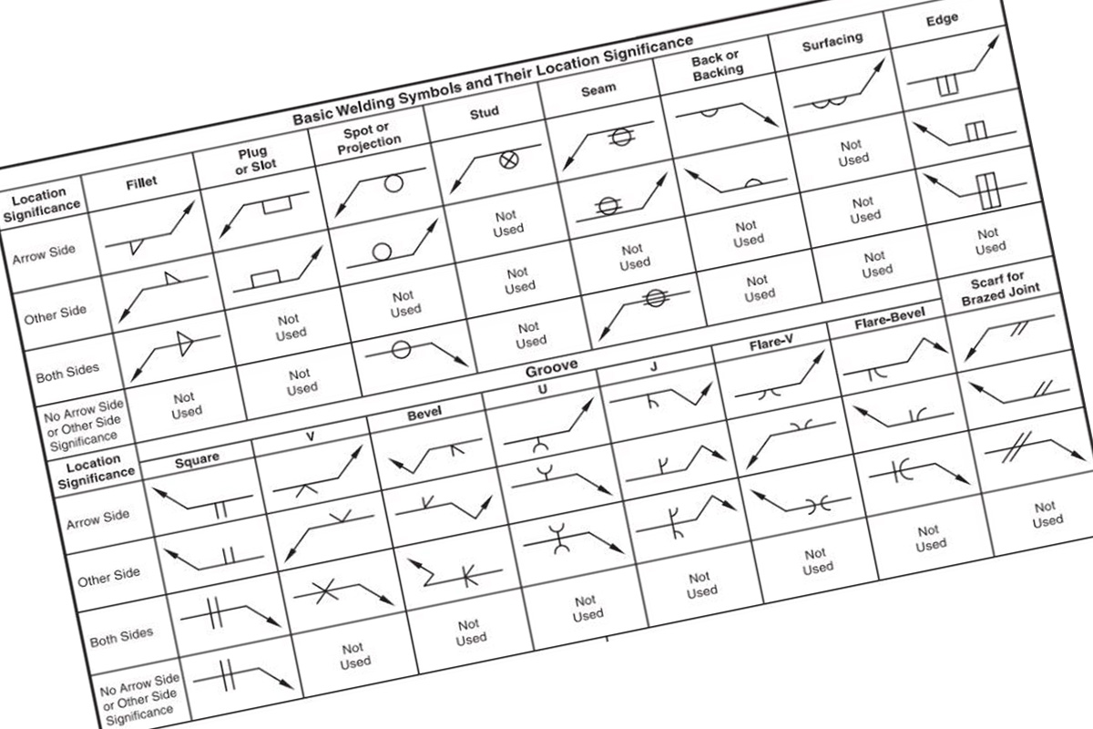 The purpose of the symbols is to indicate what welding processes are specifically being used in the joining of metals. The symbols tell whether this is a localized weld, geared toward a specific area, or whether it is the universal welding process that is used. It also depicts whether the weld was conducted in the field at the site or has been done in shop. The contour of the weld is also depicted.
There are several basic welding symbols. There are five main types, which include arc and gas weld symbols, induction and flow weld symbols, forbe thermit, brazing, and resistance weld symbols.
The purpose of the symbols is to indicate what welding processes are specifically being used in the joining of metals. The symbols tell whether this is a localized weld, geared toward a specific area, or whether it is the universal welding process that is used. It also depicts whether the weld was conducted in the field at the site or has been done in shop. The contour of the weld is also depicted.
There are several basic welding symbols. There are five main types, which include arc and gas weld symbols, induction and flow weld symbols, forbe thermit, brazing, and resistance weld symbols.
Location Significance of Arrow
We will not dig deeply into the basic welding symbols for each individual type of weld, but there are some aspects of the symbols we do want to focus on. This includes the significance of where the arrow is located. For fillet, flange, flash, groove, and upset welding symbols, the arrow is used to connect the welding symbol reference line to one side of the joint. This side is then considered the arrow side of the joint.Near Side Welding
We have learned that where the arrow connects the welding symbol reference line provides information about where the joint is located. This is important in determining where the desired weld will occur. In near side welding, the symbols depict the joint by using a single line on the drawing and the arrow as the welding symbol directed toward this line. The arrow side is then considered the near side of the joint. This is in accordance with normal conventions of drafting welding symbols.General Notes and References
We also want to provide you with some additional information about symbols that don’t have references and some general notes to consider. You will find that when the specification, process, or other type of reference is used within the welding symbol, the reference is then placed in the tail. You will find the symbols without references included when:- A note is included such as, “unless otherwise designated, all welds are to be made in accordance with specifications…”
- You will also find the symbols when the welding procedure is used to describe a location not physically at the site, such as at the shop or other processing center.
- “unless otherwise indicated, all fillet welds are to be 3/16 of an inch in size.”
- Unless otherwise indicated, rude openings for all groove welds are to be 5/16 inch in size.”
Construction of the Symbols
Here are some important rules to follow when constructing symbols:- In the case of the bevel and J-groove, fillet, flare bubble groove, and corner phalange symbols, they should be shown with the perpendicular leg always depicted to the left.
- In the case of the bevel or J-groove weld symbol, the arrow shall always point with a break depicted toward the member. This is to be chamfered. If it is easy to see that the member is chamfered, then it is perfectly acceptable to omit the break in the arrow.
- Information that are included with the welding symbols are to always be placed from left to right along the reference line. This is the required convention.
- In the case where joints have more than one weld, a symbol is required for each individual weld.
- When the letters CP are present in the tail of the arrow, this indicates that a complete penetration in the welding area has occurred.
- There may be instances where welding symbols are inadequate to properly depict the desired weld. In this case, the weld is to be shown in a cross-section with as much detail provided. Symbols should not be included alone, but detailed information should be added.
- The welder can depict a sequence of operations by drawing two or more reference lines. When this occurs, the first operation is to be shown on the reference line closest to the arrow. Subsequent operations are then to be shown in sequence on other reference lines that are included.
- When testing information is included, it is to be shown on the second or third line away from the arrow.
- When a weld all around symbol is included, it is to be placed at the junction of the arrow line and reference line for each welding process.
Is It Necessary to Use a 3-Phase MIG Welder to Read Welding Symbols?
When it comes to understanding welding symbols, using the best 3-phase mig welders is not necessary. While a 3-phase MIG welder offers advantages like higher power and smoother welds, reading welding symbols requires basic knowledge of the process rather than specific welding equipment.
Some Final Notes to Add
Before ending this article, there is some additional information that needs to be included. These are not insignificant details in any way. The welder needs to ensure that they provide details about such things as:- Abrupt changes – these abrupt changes can include such things as a quick change of direction or the extent of hatching on the dimension lines.
- Hidden joints – there like they may be instances where a hidden joint may be covered by other welds. The same information that is provided for a visible joint should be provided for the hidden joint as well. The drawing should indicate the presence of any hidden joints and provide detailed information about the joint itself.
- Location of weld symbols – the location of the weld symbols is extremely important. They must be shown on the welding symbol reference line. In the case of resistance spots and resistance seem weld symbols, the welder should place them directly on the location where the desired weld will occur.
